Introduction
In the realm of electrical circuits and devices, capacitors play a fundamental role in storing and manipulating electrical energy. Whether found in simple electronic components, complex circuits, or advanced technology applications, capacitors are essential to numerous aspects of our lives. This chapter will explore the principles of capacitors, their various types, how they store and release energy, their applications in both basic and advanced electronics, and practical considerations for capacitor usage.
A capacitor is a useful device designed to store and release electrical energy. It consists of two conductive plates separated by an insulating material called a dielectric. When a voltage is applied across the plates, an electric field is established, and electric charges accumulate on the plates. One plate accumulates a positive charge, while the other accumulates an equal and opposite negative charge. This charge separation creates an electric potential difference, or voltage, between the plates. The amount of charge transferred depends on the potential difference and on the geometry of the capacitor.
Capacitors are characterized by their capacitance, which is a measure of their ability to separate and store electric charge for a given potential difference. Let Q be the magnitude of the charge on either on either plate and V be the potential difference between the plates. The ratio Q/V is called the capacitance C of the capacitor. Capacitance is typically measured in farads (F), with one farad equal to one coulomb of charge stored per volt of potential difference (1 F = 1 C/V). Since the Farad is a large unit, submultiples such as the microfarad (1μF = 10-6) and picofarad (1pF = 10-12) are used most often.
C = Q/V 1
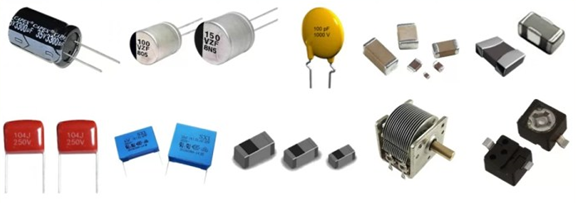
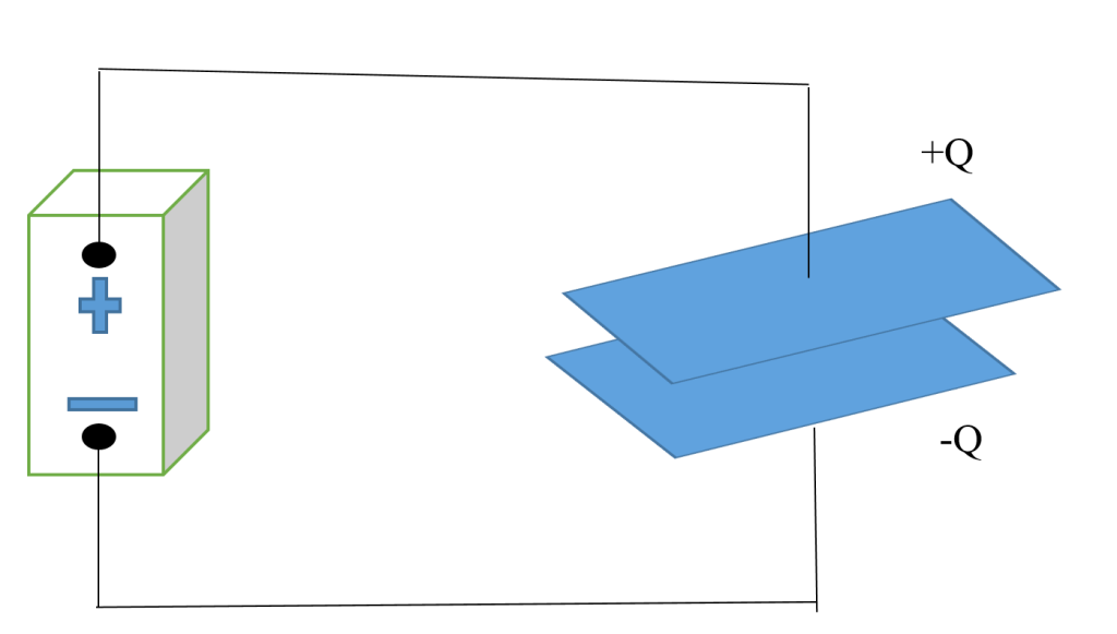
Capacitors have a wide range of applications in electronics and electrical circuits, such as energy storage, filtering, timing, signal coupling, and power factor correction. They can store energy in the form of an electric field and release it when needed. Capacitors are found in various types, including electrolytic capacitors, ceramic capacitors, tantalum capacitors, and supercapacitors, each with specific characteristics and applications. Figure 1a is a depiction of different types of capacitors while figure 1b is a typical parallel plate capacitor
There are several factors that influences the capacitance of a capacitor and they include, surface area, distance, and dielectric materials:
- Surface area is directly proportional to capacitance. A capacitor with larger plates or conductive surfaces can store more charge. This is because a larger surface area allows for more electron accumulation on one plate and an equal amount of electron depletion on the other plate, resulting in higher capacitance.
- The distance between the plates of a capacitor is inversely proportional to capacitance. As the distance between the plates decreases, the electric field between them becomes stronger, and more charge can be stored. Increasing the plate separation reduces capacitance.
- The type of dielectric material placed between the capacitor plates significantly affects capacitance. A dielectric is an insulating material that reduces the electric field between the plates. Different dielectrics have varying dielectric constants, which is a measure of their ability to reduce the electric field. A higher dielectric constant leads to increased capacitance.
To calculate the capacitance of a parallel plate capacitor, with plate area A, separated by a distance d, with a voltage difference V between them, we have to first find the electric field between the plates when they carry charges +Q and –Q. We can then use the results to find the voltage difference between the plates.
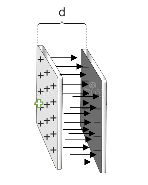
From figure 2, the electric field between the plates of the capacitor is by E = 4πkσ, where σ is the charge density on the surface of the capacitor’s plate. This charge density on a plate of area A, carrying a charge Q is
σ = Q/A 2
If we assume that the field between the plates of our capacitor is uniform, then the voltage difference between the plates equals the field multiplied by the plate’s separation distance.
⸫ V = Ed 3
Substituting E = 4πkQ/A into the above equation yields
V = Ed = 4πQd/A 4
This gives the relation between the potential difference and the charge to be:
Q = AV/4πkd 5
Dividing through by V and knowing that C= Q/V, gives us the capacitance of a parallel plate capacitor:
C = A/4πkd 6
This equation can be written as:
C = ε0A/d 7
Where ε0 = 1/4πk = 8.85×10⁻¹² C2/N·m2
From equation 7, we can see that the capacitance is proportional to the area of the plates and inversely proportional to the separation distance. It also shows that the capacitance of the parallel plate capacitor does not depend on either V or Q, but on the size, shape and geometrical arrangements of the conductors.
Example 1 A parallel plate capacitor with a rectangular plates of sides 10 cm by 8 cm is separated by a distance of 1 mm. Calculate the capacitance of this capacitor.
We will be making use of equation 7 to calculate the capacitance of this capacitor
C = ε0A/d
Where: C is the capacitance, ε0; is the vacuum permittivity, A is the area of one of the plates. d is the distance between the plates.
We have the following values: A = (10 cm) x (8 cm) = 0.1 m x 0.08 m = 0.008 m², d = 1 mm = 0.001 m
Now, we plug these values into the formula:
C = (8.85*10-12 C2/N.m2)*(0.008 m2/0.001 m)
= 7.08*10-11 F ≈ 70 pF
Example 2: If the capacitor of example 1 is connected to a 12V DC source and charged to 12V. How many charges are transferred from one plate to the other?
By rearranging equation 1, we can obtain the amount of charge transferred to either plate as
Q = CV = (70*10-12 F)*(12 V) = 8.4*10-10 C
This is the magnitude of charge on either plate.
Dielectrics
Dielectrics are materials that do not conduct electricity when exposed to an electric field. They are typically insulators, meaning they do not allow the flow of electric current, unlike conductors like metals or semiconductors. Dielectrics are crucial components in a wide range of electrical and electronic devices, including capacitors. Dielectrics play a crucial role in capacitors, and their importance in capacitor operation and design cannot be overstated. The primary role of a dielectric in a capacitor is to increase its capacitance. Capacitance is a measure of a capacitor’s ability to store electric charge for a given voltage. The presence of a dielectric material between the capacitor plates allows for the storage of more charge compared to a vacuum or air, which results in a significantly increased capacitance. This property allows capacitors to store and release energy effectively.
Dielectrics increase the capacitance of a capacitor by allowing it to store more electric charge for a given voltage. This effect is a fundamental principle in capacitor operation and can be explained through the concept of electric field, voltage, and the behavior of dielectric materials. In a standard capacitor, two conductive plates are separated by air or a vacuum. When a voltage is applied across the plates, an electric field forms between them. The electric field lines extend from one plate to the other. This field exerts a force on charged particles, such as electron. When a dielectric material is inserted between the plates of this capacitor, it changes the behavior of the electric field. Dielectrics are insulators, which means they do not conduct electric current. As a result, the electrons in the dielectric material cannot move freely in response to the electric field, as they can in a conductor.
The application of electric field across the capacitor with a dielectric inserted, the dielectric molecules or atoms become polarized as illustrated in figure 3 (a & b). In other words, the electric field induces the separation of positive and negative charges within the dielectric material, creating electric dipoles. These dipoles align themselves with the direction of the electric field. The presence of these induced dipoles within the dielectric material has a significant effect on the electric field. It effectively weakens the electric field between the plates. The electric field lines are now partly contained within the dielectric material, and the field strength is reduced.
This reduction in the electric field strength between the plates means that a greater voltage can be applied across the capacitor for a given charge. In other words, the potential difference (voltage) across the plates can increase without causing electrical breakdown. Consequently, the capacitance increases because capacitance (C) is directly proportional to the area of the plates (A) and inversely proportional to the distance between them (d):
C ∝ A/d 8
By reducing the effective distance between the plates due to the dielectric’s presence, the capacitance is significantly increased.
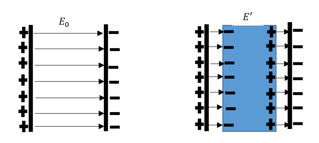
If the initial electric field in the absence of the dielectric is denoted as E0, then the electric field with the dielectric present becomes
E’ = E0/K 9
Here, Κ represents the dielectric constant. Subsequently, the potential difference between the plates can be expressed as:
V’ = E’d = E0d/K = V0/K
Here, V0 = E0d represents the initial potential difference in the absence of the dielectric. As a result, the new capacitance can be calculated as:
C = Q/V’ = (Q)/(V0/K) = K*(Q/V0) 10
We can write equation 10 as:
C = KC0 11
Where C0 = Q/V0 is the original capacitance.
In summary, the three primary functions of a dielectric in a capacitor are to increase the capacitance, enhance energy storage, and provide insulation, allowing capacitors to store and manage electrical energy effectively while maintaining their integrity and safety in various electronic and electrical applications. Table 1 is a summary of dielectric constants (relative permittivity) and dielectric strengths of various materials:
Table 1 Dielectric Constant and Strength of Various Materials
| Material | Dielectric Constant (εr) | Dielectric Strength (kV/mm) |
| Vacuum | 1.0000 | ~30 |
| Air (Dry Air) | ~1.0006 | 3-30 |
| Polyethylene | ~2.3 – 2.35 | 15-45 |
| Paper | ~2.5 – 3.5 | 6-30 |
| Mica | ~5.0 – 8.0 | 60-250 |
| Glass | ~4.0 – 10.0 | 15-40 |
| Ceramic (Barium Titanate) | ~1,000 – 7,500 | 4-20 |
| Water | ~78.5 | 65-85 |
| Silicon | ~11.7 | 300 |
| Teflon (PTFE) | ~2.1 – 2.2 | 60-100 |
| Barium Strontium Titanate (BST) | ~1,000 – 12,000 | 300-400 |
| Silicon Dioxide (Silica, SiO2) | ~3.9 – 4.2 | 10-20 |
Example 3: Determine the capacitance of a parallel-plate capacitor with plates having an area of 1 square centimetre, a separation of 1 millimetre between them, and filled with a dielectric material characterized by a dielectric constant (relative permittivity) of K = 10
We make use of the equation
C = ε0*K*A/d = (10)*(0.0001)*(8.85*10-12 C2/N.m2)/(0.001 m) = 8.85*10-10 F = 885 pF
Combination of Capacitors
The arrangement of capacitors can take various forms, each offering specific advantages for different applications. When capacitors are combined, they are typically connected to a power source, such as a battery, to establish a potential difference (V) between them, allowing them to store electric charge (Q). To describe the overall effectiveness of a capacitor combination in terms of storing charge, we use the concept of equivalent capacitance (C), defined as C = Q/V.
There are two commonly employed techniques for combining capacitors, each with distinct characteristics and applications: these are parallel and series combination of capacitors.
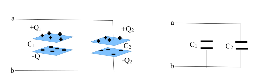
Parallel Combination
In a parallel combination, capacitors are arranged such that their terminals are connected together. This setup allows the potential difference (V) across each capacitor to be the same, as they share the same voltage source. Parallel combinations are often used when you need to increase the overall capacitance, and the individual capacitors are all connected to the same voltage source. An interesting aspect of parallel combinations is that while the potential difference across each capacitor remains uniform, the charges stored on them can be different. Each capacitor has the capacity to accumulate and hold electric charge, and this capacity is expressed as the charge (Q) associated with each capacitor. In a parallel configuration as shown in figure 4, each capacitor, denoted as C1 and C2, has its own distinct charge, referred to as Q1 and Q2. This phenomenon arises due to the individual characteristics of each capacitor, as they may possess different capacitance values or have experienced varied charging and discharging processes. Therefore, even though the potential difference across them is consistent, the charge they hold, represented by Q1 and Q2, can differ.
The charge stored on each plate of the capacitors are given by
Q1 = C1V and Q2 = C2V
Where V is the potential difference across either capacitor. The total charge stored in the capacitors arrangement then becomes
Q = Q1+Q2 = C1V+C2V = (C1+C2)V
The effective capacitance of two capacitors in parallel is the equivalent capacitance of a single capacitor that would store the same amount of charge at the same potential difference and this is defined as the ratio of the total charge stored to the potential difference. The effective capacitance is thus:
Ceff = Q/V = C1 + C2 12
When we have more than two capacitors, the equivalent capacitance can be extended to be
Ceff = C1 + C2 + C3 + C4 + C5 + ………… 13
Capacitors in parallel are used in a variety of applications, including:
- Energy storage: Capacitors in parallel can be used to store energy. This is useful for applications where a short burst of energy is needed, such as in camera flashes and electric vehicles.
- Smoothing: Capacitors in parallel can be used to smooth out a pulsating DC voltage. This is useful for applications where a smooth DC voltage is needed, such as in power supplies and audio equipment.
- Bypassing: Capacitors in parallel can be used to bypass high frequencies. This is useful for applications where high frequencies are not needed, such as in audio amplifiers and power supplies.
Example 4 Suppose we have two capacitors in parallel, with capacitances of 10uF and 20uF. The total capacitance of the two capacitors in parallel can be calculated as follows:
Ceff = C1 + C2 = 10 µF + 20 µF = 30 µF
Therefore, the total capacitance of the two capacitors in parallel is 30 µF.
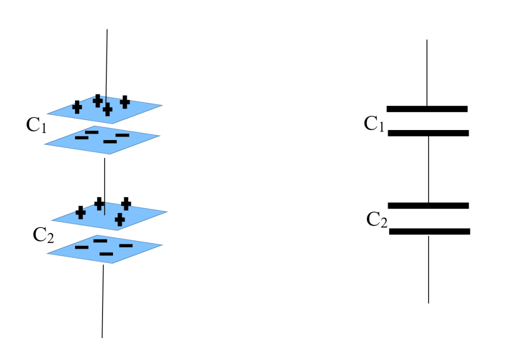
Capacitors in Series
Capacitors in series are connected one after the other, with the positive plate of one capacitor connected to the negative plate of the next as shown in figure 5. This means that the same current flows through all of the capacitors in series, while the total voltage across the combination is equal to the sum of the voltages across the individual capacitors. The total capacitance of capacitors in series is less than the capacitance of any individual capacitor. This is because the capacitors in series act like a single capacitor with a larger plate separation. A larger plate separation means less capacitance.
It is important to note that the voltages across the individual capacitors in a series combination are not necessarily equal. The voltage across each capacitor will depend on its capacitance. The capacitor with the smallest capacitance will have the highest voltage across it. The total voltage across the two capacitors are given by:
Vtot = V1 + V2
Where
V1 = Q/C1
is the potential difference across the first capacitor and
V2 = Q/C2
is the potential difference of the second capacitor.
Thus we have the total potential difference across the two capacitors to be
Vtot = (Q/C1) + (Q/C2) = Q(1/C1 + 1/C2) 14
From the above equation, the effective capacitance of two capacitors in series (which is the capacitance of a single capacitor that could replace the two capacitors) can then be calculated as:
V = Q/Ceff 15
Comparing equation 14 and 15, we then obtain: 1/Ceff = 1/C1 + 1/C2
We can then generalize to more than two capacitors connected in series, thus:
1/Ceff = 1/C1 + 1/C2 + 1/C3 + 1/C4 … 16
Capacitors in series are used in a variety of applications, including: Voltage division: Capacitors in series can be used to divide the voltage across a circuit. This is useful for applications where a lower voltage is needed, such as in power supplies and electronic devices.
Capacitors in series are a versatile component that can be used in a variety of applications. By understanding how capacitors in series work and how to calculate their effective capacitance, you can design circuits that meet your specific needs.Example 5 Suppose we have two capacitors in series, with capacitances of 10uF and 20uF. The effective capacitance of the two capacitors in series can be calculated as follows:
Ceff = (1/10 µF) + (1/20 µF) = (10 µF * 20 µF)/ (10 µF + 20 µF = 6.67 µF
Therefore, the effective capacitance of the two capacitors in series is 6.67uF.
Capacitors can be connected in series or parallel, or in a combination of both. To find the total capacitance of a network of capacitors, we can identify the parts of the network that are connected in series or parallel, and then calculate the equivalent capacitance of each part. We can then repeat this process until we have calculated the equivalent capacitance of the entire network. Consider the network of capacitors shown in figure 6, we are to find the effective capacitance of the network of capacitors.
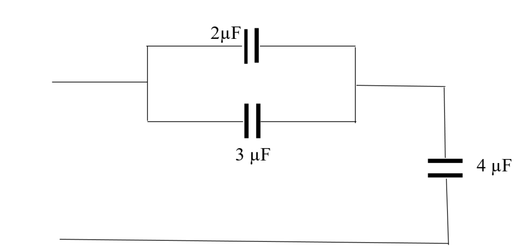
From the figure, the 2 µF and 3 µF are connected in parallel, and the parallel combination of these two capacitors is connected in series with the capacitor 4 µF. In other words, the 2 µF and 3 µF are connected together so that they share the same voltage. The combination of these two capacitors is then connected in series with the 4 µF, so that the same current flows through all three capacitors.
We then find the effective capacitance of the two capacitors in parallel to be:
Ceff = C1 + C2 = 2 µF + 3 µF = 5 µF
If we combine the two capacitors in parallel into a single capacitor with a capacitance of 5 µF, we will have a 5 µF capacitor connected in series with the 4 µF capacitor. In other words, if we connect the two capacitors in parallel and then replace them with a single capacitor with the same capacitance as the parallel combination, we will have the same circuit as before, but with one fewer capacitor.
The effective capacitance of the series combination is then given by:
1/Ceff = 1/C1 + 1/C2 = 1/5 µF + 1/4 µF = 4/20 µF + 5/20 µF
= 9/20 µF
Ceff = 20 µF/9 = 2.22 µF
Electrical Energy Storage
Capacitors can be used to store electrical energy by storing an electric charge. When a voltage is applied to a capacitor, it builds up an electric field between its plates. This electric field stores energy. The amount of energy stored in a capacitor depends on its capacitance and the voltage across it.
Capacitors can store energy very quickly, and they can release it very quickly as well. This makes them ideal for applications where a short burst of energy is needed, such as in camera flashes, electric vehicles, and medical devices. Capacitors can also be used to store energy for longer periods of time. This is done by connecting them in a series-parallel circuit. In a series-parallel circuit, the capacitors are connected in such a way that they share the same voltage, but they have different capacitances. This allows the capacitors to store more energy than they could if they were connected in series or parallel alone.
Capacitors are becoming increasingly important for energy storage, as the world transitions to renewable energy sources. Renewable energy sources, such as solar and wind power, are intermittent, meaning that they do not produce electricity all the time. Capacitors can be used to store the energy generated by renewable energy sources when it is available, and then release it when it is needed.
The energy stored in a capacitor is given by the following equation:
U = ½ (QV) = ½ (CV2) = ½ (Q2/C) 17
Where: U is the energy stored in the capacitor (in joules), Q is the amount of charge stored (in Coulombs), C is the capacitance of the capacitor (in farads), and V is the voltage across the capacitor (in volts)
This equation shows that the energy stored in a capacitor is proportional to the capacitance of the capacitor and the square of the voltage across the capacitor.
Example 5-6 A capacitor with a capacitance of 10 µF is charged to a voltage of 100 V. What is the energy stored in the capacitor?
The energy stored in the capacitor is obtained using equation 17.
U = ½ *10 µF * (100 V) = 5 mJ
This means that the capacitor can store 5 mJ of energy.
Here are some of the benefits of using capacitors for energy storage:
- Capacitors can store energy very quickly and release it very quickly as well.
- Capacitors have a high energy density, meaning that they can store a lot of energy in a small volume.
- Capacitors have a long cycle life, meaning that they can be charged and discharged many times without losing their performance.
- Capacitors are environmentally friendly.
However, there are also some challenges associated with using capacitors for energy storage:
- Capacitors can be expensive.
- Capacitors have a lower energy density than batteries.
- Capacitors can be self-discharging, meaning that they lose their charge over time even if they are not being used.
Despite these challenges, capacitors are still a promising technology for energy storage. As the technology continues to develop, it is expected that capacitors will play an increasingly important role in the global energy landscape.
Here are some examples of how capacitors are being used for energy storage today:
- Electric vehicles: Capacitors are being used in electric vehicles to provide a burst of energy for acceleration and to store energy that is regenerated during braking.
- Renewable energy: Capacitors are being used to store energy generated by renewable energy sources, such as solar and wind power.
- Medical devices: Capacitors are being used in medical devices, such as pacemakers and defibrillators, to store energy that is delivered to the patient in short bursts.
- Power electronics: Capacitors are being used in power electronics applications, such as high-frequency power supplies and uninterruptible power supplies, to filter out noise and to provide energy during short-term power outages.
As the technology continues to develop, it is expected that capacitors will be used in even more applications for energy storage.
When a capacitor is charged, an electric field is produced between its plates. The energy required to charge the capacitor can be thought of as the energy required to create the electric field. The electric field strength (E) between the plates of a parallel plate capacitor is related to the voltage difference (V) across the capacitor and the plate separation (d) by the following equation:
E = V/d
Using C = ε0A/d for the capacitance and V=Ed for the potential difference, we can modify equation 17 to read
U = ½ CV2 = ½ (ε0A/d)*(Ed)2
Or
U = ½ ε0E2(Ad) 18
Where the quantity Ad represents the volume of the space between the capacitors containing the electric field. The energy per unit volume is called the energy density η. The electric field energy density in a capacitor is the amount of energy stored in a unit volume of the electric field between the plates of the capacitor. It is given by the following equation:
η = energy/volume = ½ ε0E2 19
Where:
- η is the electric field energy density (in joules per cubic meter)
- ε0 is the permittivity of free space (in farads per meter)
- E is the electric field strength (in volts per meter)
The electric field strength between the plates of a capacitor is uniform, so the electric field energy density is also uniform. The electric field energy density in a capacitor is proportional to the square of the electric field strength. This means that the more energy that is stored in a capacitor, the stronger the electric field between the plates.
The electric field energy density in a capacitor can be used to calculate the total energy stored in the capacitor. The total energy stored in a capacitor is given by the following equation:
E = η * V 20
Where:
- E is the total energy stored in the capacitor (in joules)
- η is the electric field energy density (in joules per cubic meter)
- V is the volume of the electric field between the plates of the capacitor (in cubic meters)
This equation shows that the total energy stored in a capacitor is proportional to the electric field energy density and the volume of the electric field between the plates.
Example 7 A capacitor has a capacitance of 10 µF and a plate separation of 1 mm. The electric field strength between the plates is 100 V/m. What is the electric field energy density in the capacitor?
. η = ½ * ε0 * (100 V/m)2 = ½ * (8.85*10-12 F/m) * (100 V/m)2 = 4.425*10-7 J/m3
The total energy stored in the capacitor is:
U = η * V = 4.425*10-7 J/m3 * 10-6 m3 = 4.425*10-13 J
This means that the capacitor can store 4.425 picojoules of energy.
The electric field energy density in a capacitor is an important concept in electromagnetics. It is used to calculate the total energy stored in a capacitor and to design electronic circuits.
Questions and Solutions
- What is the capacitance of a capacitor that stores a charge of 5 μC when connected across a 10 V battery?
Solution:
C = Q/V = 5*10-6 C/ 10V =0.5*10-6 F
C = 0.5 µF
- Two capacitors, 2 μF and 3 μF, are connected in series. What is their equivalent capacitance?
Solution:
1/Ceq = 1/C1 + 1/C2 = ½ + 1/3 = 3 +2/6
Ceq = 6/5 μF = 1.2 μF.
- Two capacitors, 4 μF and 6 μF, are connected in parallel. What is the total capacitance?
Solution:
Ctotal=C1+C2
Ctotal= 4 μF + 6 μF
=10 μF
- A 10 μF capacitor is charged to a potential of 50 V. How much energy is stored in the capacitor?
Solution:
U = ½ CV2 = ½*10*10-6 F* (50V)2
= 0.5*10*10-6*2500
= 12.5*10-3 J
= 12.5 mJ
- If the distance between the plates of a parallel plate capacitor is doubled while the charge remains constant, how does the capacitance change?
Solution:
For a parallel plate capacitor, C∝ 1/d. So, if distance d is doubled, C is halved.
- What is the equivalent capacitance of three capacitors of 2 μF, 3 μF, and 6 μF connected in series?
Solution:
1/Ceq = 1/C1 + 1/C2 + 1/C3 = ½ + 1/3 + 1/6
1/Ceq = (3 + 2 + 1)/6 = 1
Ceq = 1 μF
- A capacitor of unknown capacitance is connected in series with a 5 μF capacitor. If the equivalent capacitance is 3 μF, find the unknown capacitance.
Solution:
1/Ceq = 1/C + 1/5
1/3 = 1/C + 1/5
1/C = 1/3 – 1/5
1/C = (5-3)/15 = 2/15
C = 15/ 2 = 7.5 μF
- Calculate the charge on a 0.01 F capacitor when connected to a 12 V supply.
Solution:
Q = CV
Q = 0.01 F * 12 V
= 0.12 C
- Three capacitors, each of 10 μF, are connected in parallel. What is their total capacitance?
Solution:
Ctot = 3 * 10 µF
= 30 µF
- A 2 μF capacitor and a 4 μF capacitor are connected in series across a 6 V battery. What is the voltage across the 4 μF capacitor?
Solution:
The charge on capacitors in series is the same: Q=Ceq*V
First find equivalent capacitance: 1/Ceq = ½ + ¼
Ceq = 4/3 μF
Then Q = (4/3*10-6 F) * (6 V)
= 8*10-6 C
The voltage across the 4 μF capacitor:
V = Q/C
= (8*10-6C)/ (4*10-6 F)
= 2 V.
- If a capacitor with an initial capacitance of 1 μF is filled with a dielectric material of relative permittivity 2, what is the new capacitance?
Solution:
C=κ⋅Co
=2×1
C=2×1 μF
=2μF
- Four capacitors of 1 μF, 2 μF, 3 μF, and 4 μF are connected in series. What is the total capacitance?
Solution:
1/Ceq = 1/C1 + 1/ C2 + 1/ C3 + 1/C4
= 1/1 + ½ + 1/3 + ¼
= (12 + 6 + 4 + 3)/(12)
= 25/12
Ceq = 12/25 μF
= 0.48 μF
- How much energy is stored in a 25 μF capacitor charged to a voltage of 10 V?
Solution:
U = ½ CV2
= ½ * 25*10-6 F * (10V)2
= 0.5 * 25*10-6 * 100
= 1.25 *10-3 J
= 1.25 mJ
- What is the equivalent capacitance when a 2 μF capacitor is connected in parallel with another capacitor to produce a total capacitance of 5 μF?
Solution:
Ctot = C1 + C2
5 μF = 2 μF + C2
C2 = 5 μF – 2 μF
C2 = 3 μF
- A capacitor is charged by a 12 V battery and then disconnected from the battery. If the same capacitor is now connected to a 6 V battery with opposite polarity, what will be the new voltage on the capacitor?
Solution:
The capacitor will partially discharge and then charge in the opposite direction. Assuming an ideal capacitor with no internal resistance and no energy loss, the voltage on the capacitor will simply be the voltage of the second battery, -6 V (considering the opposite polarity).